
ENGINEERED FOR THE PROCESS
Blow-through Rotary Valve
Blow-through rotary valves for direct feeding into positive-pressure pneumatic conveying lines and powder transfer systems.
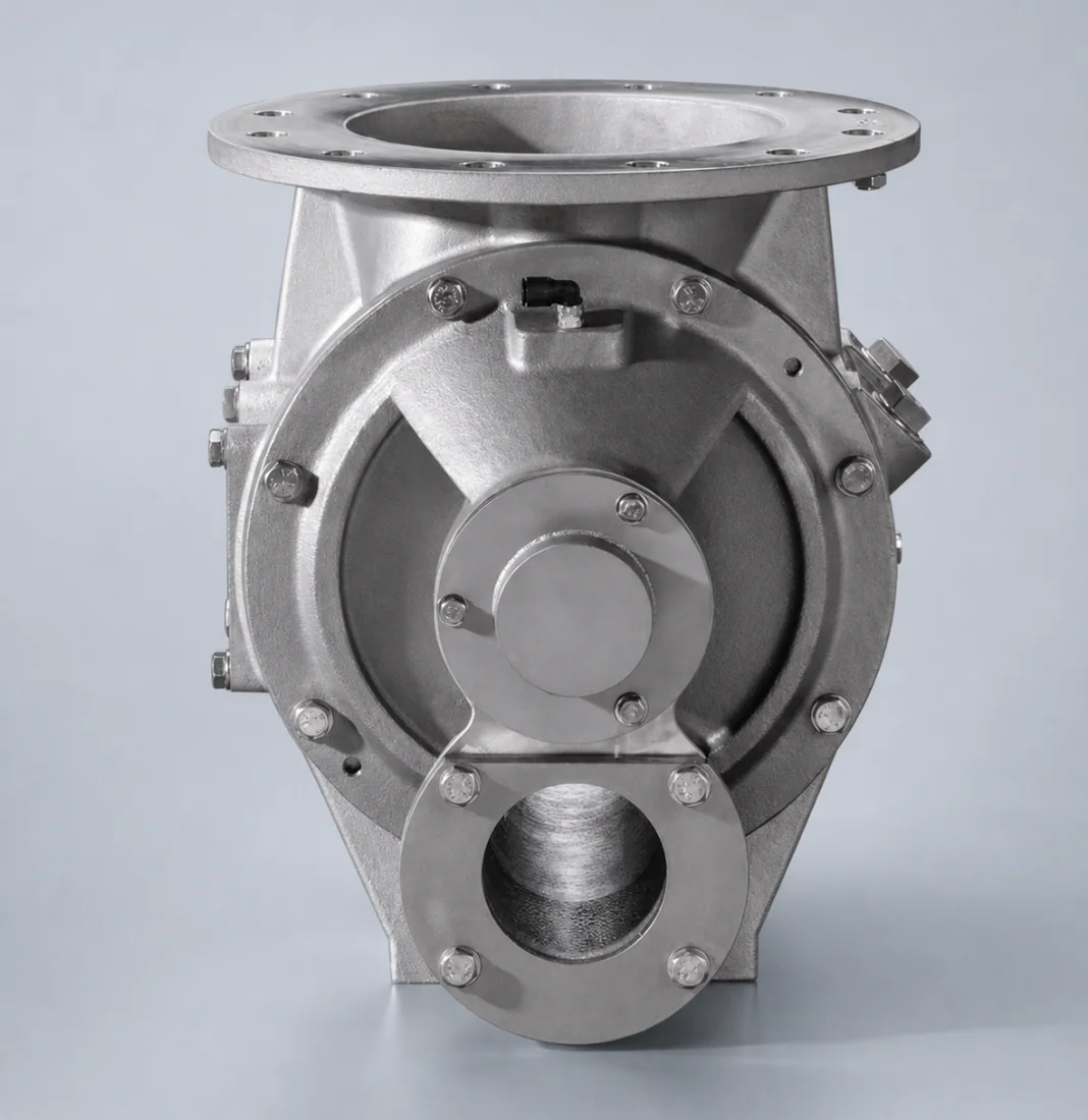
Blow-through Rotary Valve from Sercan Machinery
A blow-through arrangement feeds material into a pneumatic conveying line at the valve outlet. Selection requires both the solids duty and the conveying-line conditions; an inlet diameter alone is not enough to specify the assembly.
Typical configuration scope
- Direct pipeline connection
- Rotor design matched to conveying conditions
- Sealing options to reduce air leakage
- Custom drive speed and flange interfaces
Common applications
- Positive-pressure conveying lines
- Powder transfer systems
- Plastic granule conveying
- Cement and mineral powder feeding
Material options
- Carbon steel
- Stainless steel
- Wear-resistant liners or coatings
- Custom contact materials
COMPARE THE FEEDING ARRANGEMENT
Blow-through vs drop-through rotary valves
Blow-through: the conveying line is part of the outlet arrangement
Material enters the rotor from above and is introduced into the conveying line through the outlet arrangement. Review the line connections, air-flow direction and space around the drive together. Confirm the actual flow path on the proposed assembly drawing.
Drop-through: material falls through a lower outlet
A gravity-discharge arrangement releases material below the rotor. Where pneumatic conveying follows, include the separate pickup connection in the review. The product name alone does not establish which arrangement fits your installation.
What determines the choice?
- Solids duty: required kg/h, loose bulk density, particle size and material behavior.
- Air-system duty: pressure at the valve inlet and outlet, airflow with units and reference conditions, and conveying-pipe internal diameter.
- Interfaces: flange details, line orientation, installation height and access for maintenance.
A capacity calculation estimates rotor throughput; it does not establish conveying-line capacity, leakage performance or a pressure rating. Those require review of the proposed configuration and operating duty.
Copy this enquiry checklist
Material / particle size:
Required solids flow (kg/h):
Loose bulk density (kg/m³):
Inlet / outlet pressure and units:
Conveying airflow and reference conditions:
Pipe internal diameter / connection drawing:
Normal / maximum temperature:
Installation height / maintenance space:
Existing blockage, leakage or wear symptoms:
Unknown items needing confirmation:
Send your conveying duty for review
Paste the checklist into Requirement / notes. Send drawings separately by email or WhatsApp; this form does not upload attachments.
PROJECT-SPECIFIC SELECTION
Define the conveying-line interface
Send the solids and air-system data together
- Handled material, particle-size range, bulk density and required throughput.
- Normal and maximum pressure differential across the valve, conveying airflow and pipe internal diameter.
- Operating temperature, moisture and any tendency to stick, abrade or break during conveying.
- A layout showing the hopper, valve, line connections and maintenance space.
Confirm the connection before manufacture
Identify the inlet flange, conveying-line connection dimensions, flow direction, drive position and available installation height. Record these on the agreed drawing. A nominal pipe size does not establish flange compatibility.
Separate valve selection from conveying-system performance
State any leakage, blockage or product-degradation problem observed in the existing system. Valve selection does not by itself establish the capacity of the complete conveying line. If your installation uses gravity discharge into a separate pickup point, compare the rotary airlock valve arrangement before choosing a blow-through connection.
Prepare your project data
Use the capacity calculator for an initial estimate, the dimension checklist for interfaces, and the selection guide to compare requirements.
PROJECT FAQ
Questions about Blow-through Rotary Valve
What distinguishes a blow-through arrangement?
The conveying line passes through the outlet arrangement to carry discharged material onward. Confirm the proposed layout and connections on a project drawing rather than relying on the product name alone.
Can I select it using only the pipe diameter?
No. Provide the solids throughput, bulk density, pressure differential, conveying airflow, temperature and interface dimensions so the complete duty can be reviewed.
Will a different valve resolve a conveying blockage?
Not necessarily. Describe when and where the blockage occurs and supply the conveying layout and operating data. The cause may also involve the material, air system or pipeline.